Stimulus Isolator BVISO100 for Artifact Minimization
BVISO100 is a stimulus isolator equipped with the basic performance
and practical auto-calibration functions required for
electrophysiology experiments.
It is designed with an
emphasis on usability in research and is suitable for experiments
requiring precise measurements.
Main Features
- Easy switching between voltage output and current output
- Support for analog input and pulse input (2 channels)
- High-precision automatic calibration function
- Capacitance balance adjustment to suppress stimulus artifacts
- Real-time monitoring of output voltage and current
- Software included (monitor waveform display, CSV format data saving support, etc.)
Applications
- General electrophysiology experiments
- Electrical stimulation of brain slice preparations
- Pacing of cardiac tissue samples
Why is isolation required?
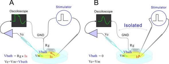
Stimulus isolator is an essential device for achieving electrical isolation in electrophysiology experiments.
Prevention of Interference with Recording Systems
In non-isolated stimulus devices, stimulus current flows through the entire solution or via ground electrodes, causing voltage increases in the chamber solution. This phenomenon makes accurate measurement of the target cell membrane potential difficult.
Control of Current Pathways
Non-isolated stimulus devices may allow current to flow through unexpected pathways within biological tissue, creating risks of unintended stimulation at unwanted sites.
Features of BVISO100
Input Functions: Support for Both Analog and Pulse
The BVISO100 supports both analog input and 2-channel pulse input to meet the needs of electrophysiology experiments. These inputs are isolated through optical isolators and transmitted to subsequent signal processing sections.
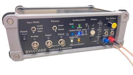
Input mode switching can be easily performed with the "Input Mode" switch on the front panel.
Analog Input
Provides the function to isolate low-voltage signals (±1V or ±5V) and linearly amplify them to high voltage (±100V). The BVISO100 can be utilized as a linear isolator.
While it incorporates feedback circuits for improved linearity, approximately ±2% error exists.
When using analog input, operation is possible without dedicated software, supporting standalone operation.
Pulse Input (2 channels)
Converts TTL-level digital signals (0V/5V, threshold 1.4V) to arbitrary high-voltage pulse outputs. It features two independent channels: Pulse1 and Pulse2.
When using pulse input mode, USB connection to a PC and configuration with dedicated software are required. The pulse height (voltage or current) for each channel is set through software.
Output Functions: Voltage/Current Switching Capability
Voltage output and current output can be switched according to experimental conditions.
Switching is performed using the "Mode" switch on the front panel or the "Mode" button in the software.
Voltage Output (CV Mode)
Function to output voltage corresponding to input at a constant level regardless of load resistance. Output voltage range is ±100V, with current limited to a maximum of 3mA.
Current Output (CC Mode)
Function to output constant current, with voltage changing according to load resistance. Output current range is 0-1mA, with three selectable ranges: 1.0mA, 0.3mA, and 0.1mA.
Advanced Automatic Calibration Functions
The BVISO100 incorporates advanced automatic calibration functions to improve experimental accuracy and reliability.
It automatically compensates for problems caused by internal circuit variations and electrode characteristic changes, providing stable stimulus output and measurement environment.
Automatic Zero Calibration
Used primarily for the following purposes:
-
Offset correction:
Automatically adjusts offsets generated by temperature changes in internal circuits, maintaining output at zero -
Response to electrode polarization voltage:
In voltage output mode, zero calibration with output ON executes offset adjustment matched to the fixed potential difference of electrodes, canceling fixed potential differences when using dissimilar metal electrodes and suppressing steady current flow
Execution can be initiated with the "Calibration - Zero" button on the front panel or the "AutoZero" button in the dedicated software.
Automatic Capacitance Calibration
Aims to provide phase compensation for delays caused by electrode resistance and maintain fast rise times of output pulses.
Can be executed with the "Calibration - Capacitance" button on the front panel or the "Cap.Comp" button in the dedicated software.
Capacitance Balance Adjustment Function
Function to cancel capacitive current caused by capacitance between the isolated section and ground. It minimizes artifacts from electrical stimulation and achieves high-precision electrode recording.
This function is not automatic adjustment but a manual adjustment method that observes artifacts appearing in recording electrode waveforms.
In an ideal stimulus isolator, input and output are completely isolated, providing accurate output current according to input. However, complete isolation is difficult in reality. For time-varying signals, isolation problems due to capacitance occur even when electrical resistance is infinite. Even a mere 10pF of capacitance can generate artifacts that significantly impact electrophysiology experiment measurements.
Internal circuit boards, cases, and wiring from the device to the sample also form capacitance. The BVISO100 main unit has approximately 50pF of capacitance, and connecting the included electrode cable adds approximately 20pF more, potentially resulting in a total of 60-70pF of capacitance. When such capacitance exists, solution potential changes are superimposed on measured membrane potentials, or temporary spike-like noise (artifacts) occurs, hindering accurate signal observation.
Real-time Monitoring of Output Voltage and Current
The system incorporates functions to monitor output voltage and current in real-time during electrophysiology experiments. Detailed waveform observation and numerical data confirmation are possible through main unit LED display and dedicated software.
This enables immediate understanding of stimulation conditions and rapid response when problems occur.
Additionally, by recording monitored voltage and current values, experiments can be conducted under highly reproducible stimulus conditions based on numerical values rather than relying on intuition from subsequent experiments.
Monitor Function Overview
-
Main unit LED display:
LEDs on the BVISO100 main unit display output voltage and current status -
PC waveform observation and measurement data display:
Connect to PC via USB interface and observe output waveforms in detail on dedicated software
Dedicated Software Functions
Dedicated software is included that enables visual understanding of detailed stimulation conditions and saves measurement data.
- Setting voltage/current values and saving/loading setting values
- Real-time monitoring of output voltage/current and waveform display
- Saving measurement values in CSV format
Voltage/Current Value Setting
Functions for setting stimulus pulse height and saving/loading setting values.
-
 Voltage value setting
-
 Current value setting
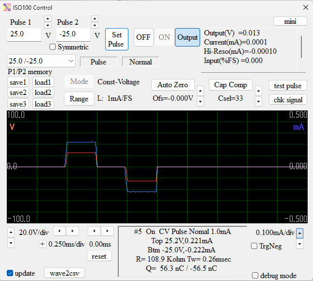
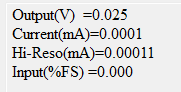
Real-time Monitor Function
Provides access to detailed output information that cannot be fully understood through main unit LED display.
Displays output voltage, output current, 10x resolution output current, and input voltage at regular intervals.
Displays measurement results of output voltage and current from stimulus pulses.
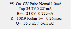
- Setting conditions: Measurement serial number, output ON/OFF, CV/CC mode, analog/pulse input source, polarity (positive/inverted), current range, etc.
- Measured values: Top voltage/current for positive direction maximum, Btm voltage/current for negative direction maximum
- Calculated values: Resistance value calculated from current and voltage (R(K立)), measured pulse width (Tw=), injected charge amount for both positive and negative pulse values (Q=) (in nC units)
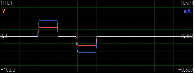
Waveform Display Function
In the software's waveform display area, output voltage and current waveforms can be visually confirmed.
CSV Saving Function for Measured Values
Function to save output voltage and current waveform data as CSV format files.
Test Functions
Software-specific test functions such as "Test pulse" that outputs pulses according to setting values and "chk signal" that outputs continuous rectangular waves for electrode resistance confirmation are also available.
Specifications
| Output | ||
|---|---|---|
| Number of Output Channels | 1 | BNC connector |
| Output terminal | SMA connector | |
| Output | Voltage or Current | Can be changed by buttons or software |
| Output Voltage Range | -100V - +100V | |
| Output Current Range | 0 - 1mA | Up to 3mA when using CV mode |
| Configurable current range | 0.1mA / 0.3mA / 1.0mA | |
| Rise Time | 2-10μsec | |
| Polarity | Reversible | Manual Switch |
| Output cutoff | Manual button or automatic shutoff when overloaded | |
| Test Output | Pulse (check settings) / Continuous square wave (check pole resistance) | |
| Input | ||
| Number of input channels | 3 (analog x1、pulse x2) | BNC connector |
| Input switching | Manual Switch | |
| Input Voltage Range |
Analog: ±1V or ±5V (input impedance: 100KΩ/12KΩ, linearity
error: ±2%) Pulse: TTL level (Vth: 1.4V, input impedance: 10KΩ) |
|
| Input isolation method | Optical isolation | |
| Various functions | ||
| Automatic Zero Calibration | Automatic calibration of offset caused by temperature changes in the internal circuit and polarization voltage of electrodes | Manual switch or software |
| Automatic Capacitance Calibration | Maintains fast rise by compensating for capacitance between output lines due to wires and electrodes | Manual switch or software |
| Capacitance Balance Adjustment | Cancellation of capacitive currents due to capacitance between insulation and ground | Manual dial + manual switch |
| Output Monitor | Main unit LED lighting and waveform observation on PC | |
| PC and Software | ||
| PC interface | Settings and display can be done on a PC | |
| Software | Included | No software required when triggering via analog input |
| Supported OS | Windows 10/11 | |
| Measurement value output format | CSV file | |
| Components, dimensions and weight | ||
| Components | BVISO100 Stimulation Isolator Unit / USB2.0 Cable / AC Adapter Electrode Cable / Software and USB Driver | |
| Power | AC adapter: 12V/0.5A | |
| Dimensions/weight | AC adapter: 12V/0.5A | W250mm x H90mm x D170mm / 1.5Kg |
* This product is for research use only. * This product is made in Japan.